MPU6050이 I2C 통신을 사용하는 방법에 대해 80% 정도 이해한 후 작성하였습니다.
ESP8266 에서 가속도/자이로 측정하기 위해 MPU6050 모듈을 사용하였습니다. MPU6050에는 X,Y,Z 축방향의 가속도센서와 온도센서 자이로센서가 있습니다. 수집된 데이터는 I2C 방식을 이용하여 데이터를 주고 받습니다.
1. I2C 통신방식은 무엇인가?
I2C은 (Inter-Integrated Circuit, eye-squared-C)의 약자로 데이터를 주고받을 수 있는 선과(SDA, Serial Data Line) 송수신 타이밍을 알려주는 선으로(SCL, Serial Clck Line) 그리고 풀업저항으로 이루어져 있다.(풀업저항은 SDA, SCL의 기본상태를 high 로 만들어주기 위해서 연결된다, 아두이노나 ESP8266에서는 내부적으로 연결되어 있다) 1)

2. 데이터를 어떻게 주고 받나?
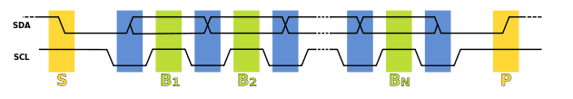
Master와 slave간에는 SDA와 SCL을 통해서 데이터를 주고받게 된다. SCL와 SDA가 high 상태이다가 SDA가 low로 변하면 데이터를 받는다는 신호를 보내게 된다. (그림에서 노란 S부분) 이후에 SCL이 high일때(녹색) SDA가 high 혹은 low 상태에 따라서 bit (0 or 1) 신호가 전달된다.
데이터를 보낼때에는 address라고 어떤 장치(데이터위치)인지 알려주는 주소값을 보내고 이후 데이터를 주고받게 된다. 7bit addressing에서는 I2C address field라고 써있는 부분(그림3)에서 장치의 address를 알려주고 8번째 자리(R/W)는 현재 데이터가 읽기인지 쓰기인지 확인하고 ACK/NACK에서 는 A(Acknowledge)로 데이터가 같은 주소의 장치인지 아닌지 확인하는 메시지를 보낸 다음 맞으면 뒷부분의 데이터를 읽게 된다. (address는 센서의 데이터시트에서 확인할 수 있다.)


master와 slave가 통신하는 것을 살펴보면 master에서 주소가 01011011이라는 신호를 SCL을 보내게 된다. 그럼 slave중에서 주소가 맞는 장치는 ACK 응답신호로 low을 보내고 나머지는 반응하지 않고 high를 유지한다.


master는 주소프레임 이후에 연결되는 데이터를(8비트) 다시 보내면 이전에 응답한 slave만 데이터를 받고 받았다고 응답메시지를 다시 보낸다. 이와같은 과정이 반복되다 종료신호를 받으면 통신이 종료된다.


3. 예제코드 살펴보기
아두이노 IDE에서 Wire.h 를 사용하여 I2C 통신을 주고받을 수 있다. 먼저 MPU의 주소를 지정해준다.(0x68, 장치를 리셋하는 주소) 그리고 가속도, 자이로, 온도값을 정수값으로 정해준다.
// (c) Michael Schoeffler 2017, http://www.mschoeffler.de
// https://mschoeffler.com/2017/10/05/tutorial-how-to-use-the-gy-521-module-mpu-6050-breakout-board-with-the-arduino-uno/

#include "Wire.h" // This library allows you to communicate with I2C devices.

const int MPU_ADDR = 0x68; // I2C address of the MPU-6050. If AD0 pin is set to HIGH, the I2C address will be 0x69.

int16_t accelerometer_x, accelerometer_y, accelerometer_z; // variables for accelerometer raw data
int16_t gyro_x, gyro_y, gyro_z; // variables for gyro raw data
int16_t temperature; // variables for temperature data

char tmp_str[7]; // temporary variable used in convert function

char* convert_int16_to_str(int16_t i) { // converts int16 to string. Moreover, resulting strings will have the same length in the debug monitor.
  sprintf(tmp_str, "%6d", i);
  return tmp_str;
}
초기 셋업에서는 ESP8266이 사용하는 baud rate 115200을 설정하고, SDA와 SCL의 핀을 지정해주고 wire에 사용되는 함수들을 이용해서 데이터를 초기화시켜준다.
void setup() {
  Serial.begin(115200);
  Wire.begin(4,5);
  Wire.beginTransmission(MPU_ADDR); // I2C slave와 MPU 주소로 데이터 전송시작 (GY-521 board)
  Wire.write(0x6B); // slave 주소값에서 장치를 깨우는 데이터를 불러오기(센서)
  Wire.write(0); // slave에 0을 넣어 MPU6050 깨우기 (wakes up the MPU-6050)
  Wire.endTransmission(true); // 전송모드
}
반복되는 작업을 살펴보면 이번에는 slave에서 0x3B 주소의 데이터를 불러오는 것을 볼 수 있다. endTrasmission(false)에서 신호가 종료되지 않고 계속해서 읽어주고 requestFrom는 MPU_ADDR(0x68) 주소에서 데이터를 리셋한후 ( 위 데이터시트 참조) 요청하는 이어지는 데이터의 갯수를 나타낸다. 여기에서는 7*2 총 14개의 데이터를 요청하는 것을 확인 할 수 있다.
void loop() {
  Wire.beginTransmission(MPU_ADDR);
  Wire.write(0x3B); // starting with register 0x3B (ACCEL_XOUT_H) [MPU-6000 and MPU-6050 Register Map and Descriptions Revision 4.2, p.40]
  Wire.endTransmission(false); // the parameter indicates that the Arduino will send a restart. As a result, the connection is kept active.
  Wire.requestFrom(MPU_ADDR, 7*2, true); // request a total of 7*2=14 registers
데이터시트를 살펴보면 0x3B 부터 가속도/온도/자이로 값이 2개씩( 값이 high 혹은 low 일때) 총 14개의 주소가 할당되어 있는 것을 볼 수 있다. 그래서 requestFrom 에서 요청한 14개 데이터는 가속도/온도/자이로 값을 받게된다.

각각의 센서값이 Wire.read()<<8 | wire.read() 와 같은 형식으로 표현되어 있다. << 와 | 는 비트연산자로 <<은 비티데이터를 왼쪽으로 8자리 옮긴다는 뜻이고 | 은 양쪽의 데이터를 비교했을때 어느한쪽에 있으면 포함시키는 연산자이다.
Wire.read()를 한번 할때마다 14의 데이터가 순서대로 불러와진다. 예를들어) 0x3B의 첫 데이터가 10100001 이고 0x3C가 00000010 이면
처음 Wire.read() 할때 1010001 이 불러와지고 <<8 비트시프트로 인해 10100001 00000000 이되고 뒤에 Wire.read()에 의해 00000010 불러와진다. 그다음 10100001 00000000 과 00000010 을 비교해서 합치면 10100001 00000010 값이 나오게 된다. 그럼 10100001 00000010 값이 x축의 가속도 값으로 계산된다. ( << 와 | 을 이용해서 두개의 비트값을 합쳐주는 것이라고 한다)
마찮가지로 이어지는 센서값들을 데이터시트의 순서대로 high와 low일때 값을 묶어줄 수 있다.
 // "Wire.read()<<8 | Wire.read();" means two registers are read and stored in the same variable
  accelerometer_x = Wire.read()<<8 | Wire.read(); // reading registers: 0x3B (ACCEL_XOUT_H) and 0x3C (ACCEL_XOUT_L)
  accelerometer_y = Wire.read()<<8 | Wire.read(); // reading registers: 0x3D (ACCEL_YOUT_H) and 0x3E (ACCEL_YOUT_L)
  accelerometer_z = Wire.read()<<8 | Wire.read(); // reading registers: 0x3F (ACCEL_ZOUT_H) and 0x40 (ACCEL_ZOUT_L)
  temperature = Wire.read()<<8 | Wire.read(); // reading registers: 0x41 (TEMP_OUT_H) and 0x42 (TEMP_OUT_L)
  gyro_x = Wire.read()<<8 | Wire.read(); // reading registers: 0x43 (GYRO_XOUT_H) and 0x44 (GYRO_XOUT_L)
  gyro_y = Wire.read()<<8 | Wire.read(); // reading registers: 0x45 (GYRO_YOUT_H) and 0x46 (GYRO_YOUT_L)
  gyro_z = Wire.read()<<8 | Wire.read(); // reading registers: 0x47 (GYRO_ZOUT_H) and 0x48 (GYRO_ZOUT_L)
구해지는 값을 문자로 변환하여 serial 을 통해 출력하면 센서값을 확인 할 수 있다.
  // print out data
  Serial.print("aX = "); Serial.print(convert_int16_to_str(accelerometer_x));
  Serial.print(" | aY = "); Serial.print(convert_int16_to_str(accelerometer_y));
  Serial.print(" | aZ = "); Serial.print(convert_int16_to_str(accelerometer_z));
  // the following equation was taken from the documentation [MPU-6000/MPU-6050 Register Map and Description, p.30]
  Serial.print(" | tmp = "); Serial.print(temperature/340.00+36.53);
  Serial.print(" | gX = "); Serial.print(convert_int16_to_str(gyro_x));
  Serial.print(" | gY = "); Serial.print(convert_int16_to_str(gyro_y));
  Serial.print(" | gZ = "); Serial.print(convert_int16_to_str(gyro_z));
  Serial.println();

  // delay
  delay(1000);

raw데이터로 얻어지는 값들을 교정하기 위해서는 시간과 오차에 대한 보정값을 계산해 줘야한다. 5)
참고
1)
https://en.wikipedia.org/wiki/I%C2%B2C
2)
https://www.circuitbasics.com/basics-of-the-i2c-communication-protocol/
Basics of the I2C Communication Protocol
The I2C communication protocol combines the best features of SPI and UART. This guide will show you how it works in an easy to understand format.
www.circuitbasics.com
3)
https://www.arduino.cc/en/Tutorial/LibraryExamples/MasterWriter
Master Writer/Slave Receiver
Open-source electronic prototyping platform enabling users to create interactive electronic objects.
www.arduino.cc
4)
https://invensense.tdk.com/wp-content/uploads/2015/02/MPU-6000-Register-Map1.pdf
5)
https://futurelab3d.com/arduino-and-mpu6050-accelerometer-and-gyroscope-tutorial/
Arduino and MPU6050 Accelerometer and Gyroscope Tutorial | FutureLab3D
In the first example, using the Processing development environment, we will make a 3D visualization of the sensor orientation, and in the second example we will make a simple self-stabilizing platform...
futurelab3d.com
'만들기 > 아두이노' 카테고리의 다른 글
| 아두이노 DC모터 움직이기( 건전지 전류용량 차이) (0) | 2021.06.26 |
|---|---|
| [밸런싱로봇] PID 제어 이해하기 (1) (0) | 2021.06.25 |
| esp 8266에서 DHT 온습도센서 2147483647 혹은 nan 오류 (0) | 2021.06.25 |
| MPU 6050 센서값 보정하기 ( 90% 이해) (1) | 2021.06.22 |
| [로봇] 밸런싱로봇 만들기 (2) (GY-521 MPU6050 ) (0) | 2021.06.20 |


